When designing a beam, it is also necessary to ensure that the deflections are acceptable. While a flexible beam might have adequate strength, excessive deflections can damage finishes like ceiling drywall and floor tiles. Floor beams may need to be checked for vibrations as well. Excessive floor vibrations due to the activities of the occupants (e.g. walking, dancing, etc.) perceived by people in the building might make them uncomfortable. Some degree of rigidity and vibration resistance is required in order for the general public to feel confident in the structure's safety.
In order to calculate deflections or the structural demand of a beam, it is necessary to know the applied load and the beam span. That's fine if you're evaluating the strength of an existing beam or if you're sizing beams based on where the architect has allowed you to have columns or load-bearing walls. In these cases the span of the beam has been determined and a the engineer needs to size the beam to safely carry the design loads. But what if, for whatever reason, you already have the size of the beam and want to know how far apart you can place supports? This scenario might be encountered in a preliminary design stage, especially if you're attempting to develop an economical design using standard material sizes and spacing. For example, perhaps you want to minimize the cost per square foot of a wooden deck constructed using 2x8 lumber.
Calculating maximum spans might start to get cumbersome if you've got to consider multiple load patterns and failure modes. However, there are many scenarios where you can simplify things enough that having a maximum span table makes sense, such as in wood floor design. In this post I derive some formulas that can be used to calculate maximum beam spans. I have assumed that the beams are supported at the ends only, the ends are free to rotate about the axes perpendicular to the length of the beam, and the beams are subjected to a uniformly distributed load. The shortest span calculated after checking all possible failure modes would be the maximum permissible span.
Failure Mode: Shear strength
The demand on the beam is the maximum applied shear force, Vf. For a beam with uniformly distributed load w, the maximum applied shear force is:

A beam's maximum resistance to shear, Vr, is the product of some allowable shear stress and the beam's effective shear area. In stocky beams, the allowable shear stress depends only on the strength of the material that the beam is made from. In thin-walled beams, allowable shear stress may be reduced due to buckling, in which case the maximum shear stress is a function of other factors, such as the depth-to-thickness ratio of the beam web.

 |
| Maximum beam span for shear-controlled failure |
Failure Mode: Bearing strength
The demand on the bearing is the maximum support reaction force. Since the beam is supported only at either end, the maximum support reaction is also equal to the maximum shear force. Bearing resistance is determined by the bearing contact area multiplied by some allowable bearing stress, which could be limited by the strength of either the beam or the support material.

Fcp is the allowable stress in compression perpendicular to the beam and Ab is the area of bearing.
 |
| Maximum beam span for bearing-controlled failure |
Failure Mode: Bending strength
The demand on the beam is the maximum applied bending moment, Mf. For a beam with uniformly distributed load, the maximum applied bending moment is:

A beam's maximum resistance to bending, Mr, is the product of some allowable bending stress and a property of the cross-section known as the section modulus, S. In stocky beams, the allowable bending stress depends only on the strength of the material that the beam is made from. In thin-walled beams, allowable bending stress may be reduced due to distortional or local buckling effects. The spacing of lateral supports keeping the beam aligned can also reduce the allowable stress due to the effect of lateral-torsional buckling.

The beam's resistance to bending failure must exceed the demand in the beam (Mr > Mf). Therefore, the maximum beam span for bending-controlled failure is:
 |
| Maximum beam span for bending-controlled failure |
Failure Mode: Excessive absolute deflection
The deflection of a beam under uniform load is typically calculated from:

where E is the modulus of elasticity and I is the moment of inertia (second moment of area). Therefore, the maximum beam span to ensure the deflection does not exceed the maximum permissible value is calculated from:
 |
| Maximum span for deflection control |
This was based on the assumption that the deflections of the beam come almost entirely from bending deformations. However, shear deformations may also need to be considered in cases where the beam's span to depth ratio is low and/or if the shear rigidity of the beam is small relative to the bending rigidity. A more precise formula to calculate the deflection of a beam under uniform load is:

where k is an empirical correction factor, A is the cross-sectional area, and G is the shear modulus. Research has shown that k is dependent on both the cross-sectional shape of the beam and Poisson's ratio of the material.
Solving for L here requires you to solve for the roots of a quartic equation. But there are no cubic or linear terms here, so we can treat it as quadratic, which you might remember is something you learned to solve in high school. So, based on the more accurate deflection formula, the maximum beam span to ensure the deflection does not exceed the maximum permissible value is:
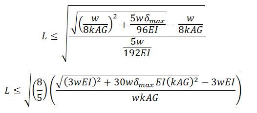 |
| Maximum span for deflection control (including deflection due to shear deformations) |
Failure Mode: Excessive deflection-to-span ratio
Instead of an absolute deflection limit, designers often choose a limiting ratio of deflection to beam span. A commonly selected maximum deflection is the span divided by 360. The span divisor, which I'll call SD, might be decreased to say 180 where the structure is not supporting anything sensitive to deflections, or it might be increased to say 800 or more where deflection-sensitive equipment is supported. The deflection of a beam under uniform load is typically calculated from:

Therefore, the maximum beam span to ensure the deflection does not exceed the maximum permissible deflection-to-span ratio is calculated from:
 |
| Maximum span for deflection control, based on limiting deflection/span ratio |

 |
| Maximum span for deflection control, based on limiting deflection/span ratio (including shear deformations) |
So what does all this mean? Well, shear and bearing are proportional to span, bending moment is proportional to span squared, and deflection is a 4th order function of span. This means that for sufficiently large values of L, deflection will govern the design. Put another way, for very lightly loaded beams, the maximum span is a deflection-controlled span. For small values of L, shear or bearing may govern the design. Equivalently, for very heavily loaded beams, the maximum span might be controlled by shear or bearing strength. Here's an example with a steel bar, 2 inches wide by 4 inches deep. I've assumed a grade of steel with 44,000 psi yield strength, E = 29,000,000 psi, and G = 11,500,000 psi. I calculated allowable bending and shear stresses in accordance with the allowable stress design equations in AISC 360-2010, assuming the bar is laterally restrained at the supported ends only. I've also assumed that bearing strength is not an issue and that deflection must be less than L/180 or 2 inches, whichever is less.
 |
| Maximum span versus applied load for a 2" by 4" steel beam. |
My ex-husband and I had always managed to stay friendly after our divorce in February 2017. But I always wanted to get back together with him, All it took was a visit to this spell casters website last December, because my dream was to start a new year with my husband, and live happily with him.. This spell caster requested a specific love spell for me and my husband, and I accepted it. And this powerful spell caster began to work his magic. And 48 hours after this spell caster worked for me, my husband called me back for us to be together again, and he was remorseful for all his wrong deeds. My spell is working because guess what: My “husband” is back and we are making preparations on how to go to court and withdraw our divorce papers ASAP. This is nothing short of a miracle. Thank you Dr Emu for your powerful spells. Words are not enough. here is his Email: emutemple@gmail.com or call/text him on his WhatsApp +2347012841542
ReplyDeleteHe is also able to cast spell like 1: Lottery 2: Conceive 3: Breakup 4: Divorce 5: Cure for all kinds of diseases and viruses.
How to Hire a Hacker to Recover Stolen Bitcoin ; Top Crypto Recovery Expert in USA
ReplyDeleteAlpha Recovery Experts delivers recovery solutions for those who have fallen victim to investment scams to get back their lost money. I was a victim of a fake cryptocurrency exchange scam and lost a substantial amount of money to the scam. I was in disbelief and discomfort as this was my hard earned money and life savings. The anxiety of losing my investment was debilitating. Desperate for a solution, I turned to the internet. I scoured forums, read articles, and even consulted with so-called “experts,” but nothing seemed to work. Just when I thought all hope was lost, I came across Alpha Recovery Experts who came to my aid and helped me recover my money. From our first interaction, Alpha Recovery Experts exuded professionalism and expertise all through the recovery process.
Fast Contact,
Visit: alpharecoveryexperts.com
Mail: alpharecoveryexpert@consultant.com
WhatsApp/Call: +447457424681